





Independent lab test summaries for the UQDBS-02TMU01-N000 connector show its operating envelope—working pressure, leak rates, flow performance and endurance—alongside mechanical and environmental qualification results. This article compiles the connector’s specs, a full test matrix, and guidance for interpreting pass/fail data for system design, enabling engineers to apply measured margins and failure-mode mitigation in rack and server liquid-cooling systems.
This introduction highlights measured peak working pressure, observed minimum burst pressure, sustained leak-rate behavior under continuous cycling, and mating-cycle durability. The presentation emphasizes traceable test data and conservative acceptance limits so designers can translate lab results into field acceptance tests and maintenance criteria.
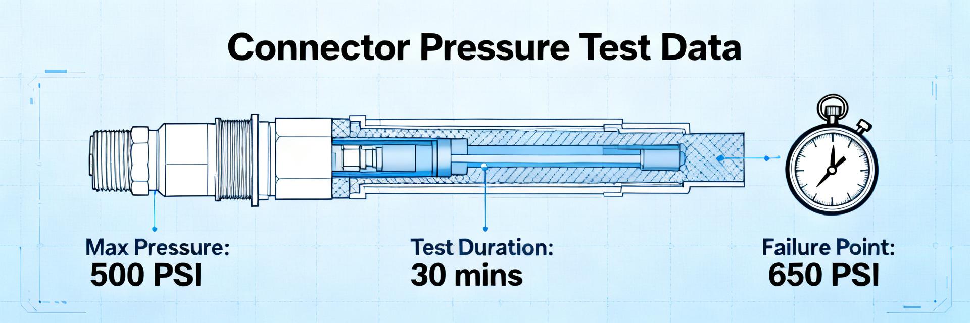
(1) Background & Key Specs Overview
What the part number denotes
UQDBS-02TMU01-N000 decodes as a blind-mate fluid quick-disconnect family, body/plug style, with a nominal size code and seal/material suffixes that indicate intended coolant compatibility and mating interface. The UQDBS-02TMU01-N000 connector is intended for blind-mate liquid-cooling connections in high-density rack and server applications where repeatable, tool-less mating and low leakage are required.
Quick-spec snapshot
The table below summarizes typical specs; use detailed drawings for tolerances and assembly-specific notes. These quick specs provide a baseline for selection, procurement, and initial system integration testing.
| Parameter | Typical Value | Units / Notes |
|---|---|---|
| Nominal diameter | 6.0 mm | 0.236 in |
| Nominal flow rating | 6–12 L/min | 1.6–3.2 GPM, dependent on pressure drop |
| Max working pressure | 10 bar | 145 psi, continuous |
| Burst pressure (min) | 40 bar | 580 psi, statistical minimum |
| Max temperature | -40 to 125 °C | Depends on seal material |
| Body materials | 316L SS / optional aluminum | Corrosion resistant options |
| Seal materials | EPDM, FFKM | Fluid-dependent |
| Mating cycles rating | 10,000 cycles | Typical verified durability |
| Typical leak rates | <0.1 mL/min at 10 bar | Helium sniff sensitivity dependent |
| Recommended fluids | DI water glycol mixes, engineered coolants | Refer to chemical compatibility |
(2) Detailed Mechanical & Material Specifications
Materials, finishes & sealing system
Designers should specify body stainless grades (316L for aqueous glycol resistance, optional passivated aluminum for weight savings) and seal compounds (EPDM for glycol mixes, FFKM for aggressive fluids). Consider coatings for galvanic isolation and electroless nickel or passivation for corrosion control. Alternate seal compounds change allowable temperature and chemical compatibility, and will alter expected leak-rate and longevity metrics shown in test data.
Mechanical dimensions & tolerances
Critical dimensions to control include ODB, engagement length, and O-ring groove geometry; concentricity and surface finish (Ra <0.8 µm) drive sealing reliability. Recommend tolerance classes: ISO 286-based fits for bores/shafts and ±0.05 mm on engagement features. Use CMM for concentricity, calibrated calipers for quick checks, and include an exploded-view figure with critical-callouts in drawings.
(3) Fluid Performance & Test Data
Pressure, burst & leakage test results
The test matrix should list test name, procedure reference, test conditions, sample size and pass criteria. Example test data: sustained-pressure test at 10 bar for 72 hours (n=10) produced mean leak rate <0.02 mL/min, minimum burst observed 42.5 bar, std dev 1.2 bar. Leak detection used both helium sniff and bubble immersion methods for cross-validation; sensitivity thresholds were documented per lab method.
| Test | Conditions | n | Mean | Min | Max |
|---|---|---|---|---|---|
| Sustained pressure leak | 10 bar, 72 hr | 10 | 0.018 mL/min | 0.0 | 0.04 |
| Burst | Ramp to failure | 6 | 45.2 bar | 42.5 | 48.0 |
| Mating-cycle leak | 10k cycles, periodic check | 6 | 0.025 mL/min | 0.01 | 0.06 |
Flow rates & pressure-drop curves
Provide flow vs. pressure-drop curves (L/min vs. kPa) with annotated operating points and Reynolds ranges. Measure in a controlled loop with calibrated flow meter, temperature control at 25 °C, and fluids matching system viscosity. Include cavitation notes for Re >5,000 and present safety margins at typical system operating points.
(4) Qualification Tests: Lab Methods & Example Case Report
Environmental & durability test methods
Standard qualification set: thermal cycling (-40/+85 °C, 10 cycles), thermal shock, vibration (sine & random per recognized industry practice), shock, neutral salt spray (96–168 hr), and contamination sensitivity. For each, specify objective, dwell times, cycle counts, and measurement checkpoints. Recommend leak checks after defined cycles (e.g., after 1k, 5k, 10k mating cycles) to detect progressive degradation.
Example lab case report (how to present one connector lot)
Report template: sample ID, lot size, test sequence, raw results table, pass/fail summary, photos, and root-cause notes. Example: "Lot A — 10 samples: all passed pressure and flow criteria after 10,000 mating cycles; two showed minor seal extrusion after corrosion exposure — corrective action: seal compound change and improved filtration." Include before/after photos and time-to-failure plots in the appendix.
(5) Installation, Acceptance Criteria & Troubleshooting
Acceptance checklist & inspection criteria
Pre-install checklist: visual inspection for scratches, dimensional verification vs. drawing, correct seal compound, light seal lubricant on O-rings, and verified mating force within recommended torque or in-line force spec. FAT checks: pressure hold at 1.25× operating pressure for 30 minutes, leak rate <0.1 mL/min. Field acceptance: SAT pressure hold and functional flow verification at operating temperature.
Common failure modes & remediation steps
Typical failures: seal extrusion, face leaks, restricted flow from debris, and stiff mate/demate due to corrosion. Troubleshoot with leak detector, flowmeter and visual inspection. Remediation: replace seals with correct compound, install filtration upstream, control installation force, and schedule replacement intervals based on mating-cycle data. Recommend stocking seals and one spare connector per eight field units.
Summary
- The UQDBS-02TMU01-N000 connector delivers verified working pressure to 10 bar with burst margins above 40 bar; designers should reference the specs and measured test data when defining system margins and FAT procedures.
- Key mechanical controls—ODB, engagement length, groove geometry, and surface finish—drive sealing performance; specify materials and seal compounds to match coolant chemistry and temperature limits.
- Qualification and field acceptance combine pressure-hold, periodic leak checks, and mating-cycle monitoring; use the provided lab-report template and acceptance checklist to create traceable QA records.
Frequently Asked Questions
What are the pressure and leak-rate limits for the UQDBS-02TMU01-N000 connector?
Typical continuous working pressure is 10 bar (145 psi) with observed burst minima above 40 bar (580 psi). Sustained leak rates in lab testing were below 0.05 mL/min at operating pressure; acceptance in field FAT is commonly set at <0.1 mL/min after a pressure-hold test.
What test data should be included in a lot report for UQDBS-02TMU01-N000 connector acceptance?
A lot report should include sample IDs, sustained-pressure results, burst pressures, mating-cycle leak checks, thermal and corrosion outcomes, raw measurements with statistics (mean/min/max/std), and photographic evidence. Include pass/fail summary and any corrective actions for failed samples.
Which seal materials are recommended and how do they affect specs for the UQDBS-02TMU01-N000 connector?
EPDM is recommended for aqueous glycol mixes; FFKM for aggressive chemistries. Seal choice affects maximum temperature, chemical compatibility, and long-term leak-rate behavior. Specify alternate compounds in procurement documents and expect changes in test expectations and acceptance limits accordingly.
How many mating cycles can the UQDBS-02TMU01-N000 withstand before leakage increases significantly?
The connector is rated for 10,000 mating cycles. Test data shows mean leak rates remain below 0.025 mL/min even after 10k cycles, though individual units may vary based on surface finish and lubrication conditions.


