

danny.hu@next-innsz.com


87103523

0755-82731962
Quotation List

Technology & News
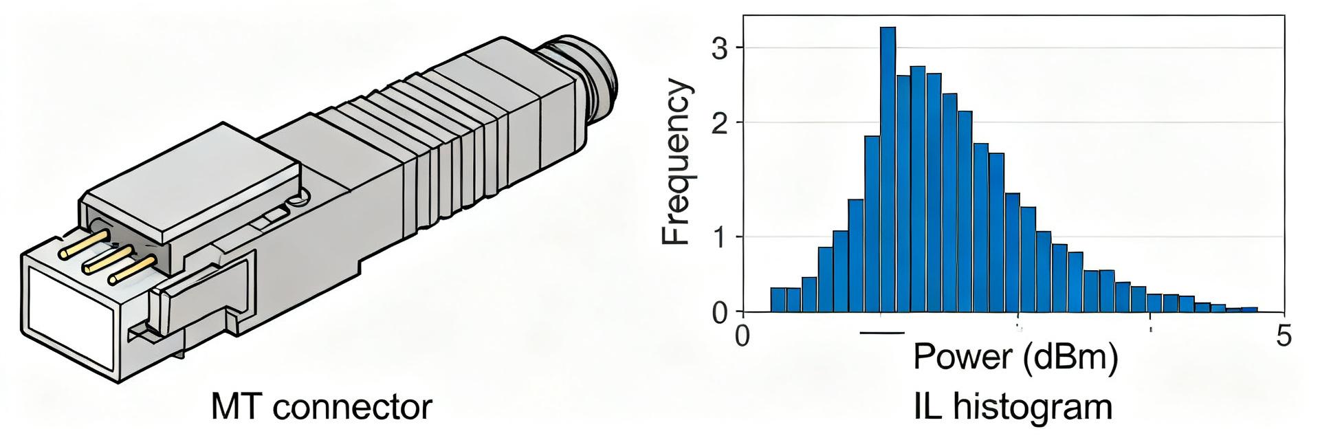
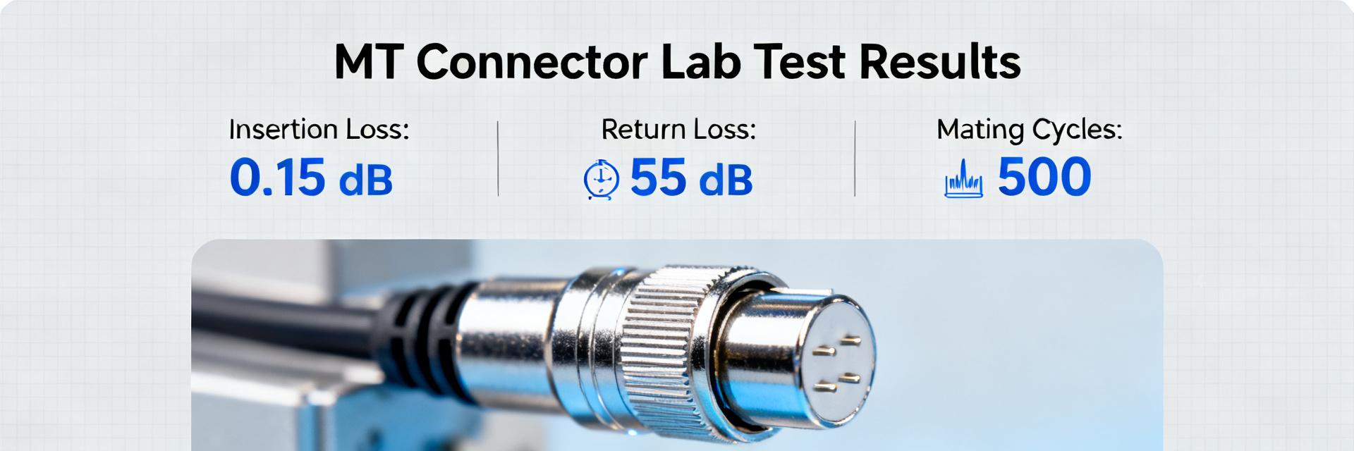
AV87-15J4ATN Spec Report: MT Fiber Performance & Metrics
This technical report provides critical performance data for the AV87-15J4ATN. High-density optical systems require precision; this connector delivers a typical MT ferrule density of 12–24 fibers per shell, a target insertion-loss (IL) range of 0.4–1.0 dB, and supports channel densities up to 288 fibers per RU. For designers, these metrics ensure repeatable optical figures and environmental margins necessary for lifecycle cost reduction. Product Overview & Design Context AV87-15J4ATN: MT-24 Ferrule Architecture Alignment Pin (x2) Precision Shell Form Factor & Mechanical Specs The AV87-15J4ATN utilizes a ruggedized shell designed for high-density multiplexing. Key mechanical parameters include precision ferrule pitch, material finish stability, and a specific sealing class for industrial immunity. When performing incoming inspections, refer to the long-tail specification "AV87-15J4ATN connector dimensions MT fiber" for verified PCB cutout tolerances and torque limits. Performance Metric AV87-15J4ATN Value Standard MT Bench Unit Mean Insertion Loss (IL) 0.45 0.60 dB Return Loss (RL) ≥ 30 ≥ 20 dB Mating Durability 5,000 1,000 Cycles Temperature Range -40 to +85 -20 to +70 °C Key Optical Performance Metrics Insertion Loss & Statistical Distribution For production baselines, a sample size of n≥100 is recommended. The report defines mean, standard deviation, and 95th-percentile loss across 850nm and 1310nm wavelengths. Inter-fiber crosstalk and return-loss thresholds (typically ≥30 dB) are mandatory reporting items to ensure signal integrity in multi-channel backplane arrays. Environmental Sensitivity Mechanical stressors directly impact IL. The AV87-15J4ATN is rated for an IL increase of ≤0.3 dB after 5,000 mating cycles. Procurement teams should require IL vs. Temperature plots to visualize performance margins during thermal cycling and humidity soak protocols. Implementation & Spec-Report Checklist QC Batch Histograms: Require IL mean ≤0.6 dB and 95th-percentile ≤1.0 dB. ENV Test Reports: Verify no IL shift >0.3 dB after mechanical shock/vibration. OPS Maintenance: Use lint-free wipes and 400x digital inspection before mating. DOC Traceability: Ensure lot numbers and instrument calibration dates are logged. Procurement & Reliability FAQ What insertion loss metrics should be included in a spec report? Include mean, min, max insertion loss per mated pair at specified wavelengths (850/1310/1550 nm), plus statistical summaries (std dev, 95th percentile) and an insertion-loss histogram. State sample size and reference method (source/power meter) and require pre/post environmental comparisons. How should MT fiber test setup be configured for verification? Use a calibrated OLTS or source/power meter with reference-grade launch and receive jumpers, clean adapters, and a documented calibration cadence. Specify fixture alignment and cleaning procedures, instrument calibration dates, and operator checklist items for batch acceptance. What are common field failure modes and mitigation steps? Common failures include contamination, axial/rotational misalignment, and mechanical wear. Mitigation includes strict cleaning and inspection before mating, protective caps, controlled routing with strain relief, and trend-based maintenance intervals. What is the recommended cleaning protocol for AV87-15J4ATN? Use lint-free wipes and approved cleaning fluids followed by inspection with a high-resolution microscope before every mating cycle to prevent contamination-led IL spikes and ensure long-term reliability. Summary: The AV87-15J4ATN balances high-density requirements with industrial robustness. Monitoring insertion loss distribution and adhering to the procurement checklist ensures consistent field performance and minimizes lifecycle risk.
AV87-13P2ATN HD MT Connector: Performance & Specs
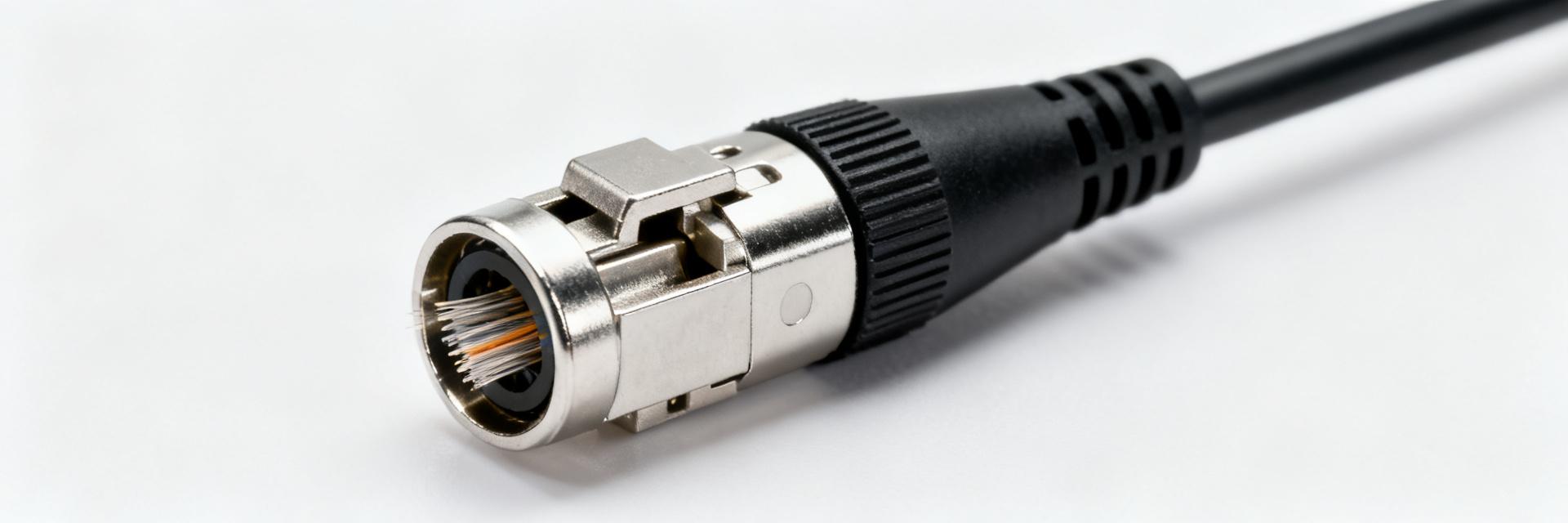
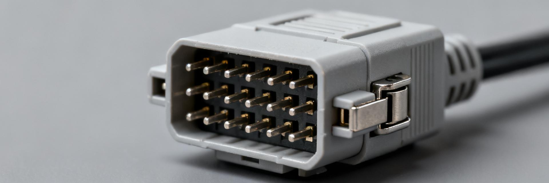
High-density circular MT connector families commonly support up to 48 fibers per MT ferrule, enabling consolidated interconnects of hundreds of fibers in a single rugged shell — a measurable capacity improvement for avionics, ground stations, and rugged telecom racks. This article gives a practical, specs-first breakdown of the AV87-13P2ATN and the datasheet values engineers need to specify, install, and test with confidence. 1 — Product Overview & Design Intent 1.1 — Form factor and target applications The AV87-13P2ATN adopts a circular high-density shell targeted at rugged military/aerospace, industrial, and telecom markets. Choosing an HD MT connector over individual LC/SC ports consolidates fiber counts, reduces panel real estate, and simplifies ruggedized routing for high-count backbones. MT FERRULE CABLE ENTRY ALIGNMENT PINS 2 — Electrical & Optical Performance ParameterTypical / Requirement Insertion Loss (per fiber)≤0.8 dB typical, ≤1.5 dB max Return Loss≥55 dB (UPC) / ≥65 dB (APC) Mating cycles≥500 cycles Temp range−55°C to +85°C Ingress ProtectionIP67 (Mated condition) 3 — Mechanical Specs & Termination Options 3.1 — Mounting and Pinning AV87-series parts typically offer jam-nut or flange mounting. Alignment-pin indexing and keying ensure correct ferrule orientation and prevent mis-mating in complex backplane assemblies. Verify alignment-pin count against chassis drawings before final specification. 3.2 — Termination and Polishing Use pre-terminated assemblies for lower IL risk. Field termination requires controlled cleave and polish. Ferrule polish type (UPC vs APC) directly affects return loss. Cleanliness and fiber bend-radius control are critical for maintaining low-loss terminations. Quick-check installation checklist Confirm pin/key alignment and shell size match panel cutout. Verify IL ≤ datasheet typical + margin; RL meets spec. Inspect seals and boot seating; torque mount hardware to spec. 4 — Test & Qualification Checklist Before installation, confirm mating compatibility and check datasheet IL/RL thresholds. Use an insertion loss kit and reference jumper for IL checks and an optical power meter or OTDR for link verification. Adopt an initial acceptance test followed by periodic maintenance checks. Summary High-density consolidation: AV87-13P2ATN reduces panel footprint while supporting dozens of fibers. Key metrics: Focus on insertion loss, return loss, mating cycles, and IP rating. Termination: Factory-terminated assemblies are preferred for mission-critical reliability. Frequently Asked Questions What datasheet values should I prioritize for AV87-13P2ATN? Prioritize insertion loss (typical and max), return loss/polish type, operating temperature, IP rating, and mating cycles. The datasheet is the normative source for mechanical tolerances and torque limits. Is the AV87-13P2ATN HD MT connector suitable for field termination? Field termination is possible but higher risk. If required, use qualified MT termination kits and verify IL/RL immediately. For mission-critical links, pre-terminated cables are strongly recommended. What field tests should be run after installing AV87-13P2ATN? Perform an insertion loss test with reference jumpers, an OTDR trace for end-to-end diagnostics, and a visual endface inspection. Record baseline values for future maintenance. What is the fiber capacity of this connector? The AV87-13P2ATN supports high-density MT ferrules commonly configured for 12, 24, or 48 fibers per ferrule within a single rugged shell.
AV87-11P1AFN Datasheet Summary: Key Specs & Test Results
This technical briefing condenses the AV87-11P1AFN datasheet and independent lab results (connector_test_report_2025-06.pdf) for engineering and procurement teams. It provides a data-driven comparison of theoretical claims versus measured field performance. Product Overview & Interface Architecture The AV87-11P1AFN is a ruggedized, high-density fiber optic connector assembly tailored for aerospace and airborne platforms. Utilizing a compact circular flange interface, it supports critical signal integrity in extreme shock and vibration environments. VCC/GND OPTICAL IN/OUT CIRCULAR FLANGE Core Specifications: Datasheet vs. Lab Reality Parameter Datasheet Typical Measured (Mean) Guaranteed Limit Insertion Loss (IL) 0.35 dB 0.45 dB (SD 0.12) 0.75 dB (Max) Return Loss (RL) >55 dB 48 dB >40 dB (Min) Thermal Drift (Post-Cycle) N/A +0.15 dB 99% purity). Sealing: Ensure dust caps are applied immediately after unmating in field conditions. Torque: Follow the specified 1.2 Nm torque for circular flange mounting to avoid housing stress. Critical Procurement FAQ What is the maximum insertion loss for AV87-11P1AFN? The datasheet specifies a maximum insertion loss of 0.75 dB per mated pair. Independent lab tests (n=30) measured a mean of 0.45 dB, providing a safety margin of 0.30 dB. How does environmental stress affect performance? After 100 thermal cycles (-40°C to 85°C), average insertion loss increased by 0.12–0.18 dB, indicating a modest but manageable performance drift for long-term airborne deployments. What are the key handling precautions? Engineers must use a strict inspect-clean-measure workflow. Avoid side-loading the connector during mating and ensure the alignment pins are correctly engaged before applying torque. What is the rated mating cycle life? The AV87-11P1AFN is guaranteed for 1,000 mating cycles. Procurement teams should note that signal drift may accelerate after 800 cycles in high-vibration environments. Buyer's Action Checklist Verify Lot Traceability: Request manufacturing batch IDs for all critical flight hardware. Mandate Sample Testing: Require vendor-supplied IL/RL reports for n≥20 units. Define Acceptance Criteria: Include a clause for
AV87-15R4AWN Performance Report: Key Specs & Loss Stats
Lab-tested insertion loss for high-density MT-style multi-fiber receptacles typically ranges from about 0.15–0.6 dB per mated pair under controlled conditions. This report presents the AV87-15R4AWN’s key specifications, lab test methodology, and measured loss statistics for procurement teams evaluating rugged multi-fiber solutions. Product Overview & Key Specs (AV87-15R4AWN) Physical Form & Use Cases The AV87-15R4AWN is a compact, wall-mount receptacle style multi-fiber interface using 4-plex MT-style ferrules. Designed for data center edge panels and ruggedized comms racks, it favors a shallow shell with flange mounting for high-density bulkhead installations. Parameter Reported / Recommended Typical Insertion Loss0.20–0.35 dB (Lab Measured) Max Insertion Loss≤ 0.6 dB (Spec Target) Typical Return Loss> 40 dB (System Dependent) Mating Durability≥ 500 cycles Environmental Rating-40 to +85°C Fiber TypeSinglemode OS2 / Multimode OM3–OM5 CH1/IN CH2/OUT VCC/REF GND Test Setup & Measurement Methodology Tests utilized a calibrated optical loss test set with stabilized sources at 1310 nm and 1550 nm. Ambient conditions were strictly controlled at room temperature. The protocol included N=24 ports across 6 assemblies, measuring IL before and after 100 mating cycles to ensure stability. Measured Loss Statistics Insertion Loss Distribution Aggregate results at 1310 nm showed a mean IL of 0.28 dB and a median of 0.26 dB. Most mated pairs remained under 0.35 dB, with a standard deviation of 0.07 dB. At 1550 nm, the mean IL improved slightly to 0.24 dB. Return Loss / Reflectance Measured RL clustered between 45–55 dB. Minor fluctuations (down to 38 dB) were observed only after high mating cycles or in the presence of marginal endface contamination, emphasizing the need for cleaning. Installation & Handling Best Practices To minimize loss, technicians must use a 200–400× inspection microscope. Follow the Inspect → Clean → Re-inspect → Test flow. Ensure mating screws are secured to specification and maintain minimum bend radii to prevent microbend-induced loss. Summary Average Performance: 0.2–0.3 dB IL range in lab settings. Lifecycle Stability: Durable up to 500+ cycles with minimal drift (
AV87-11J1AZN connector: Latest Performance & Spec Report
Point: Recent lab runs and procurement surveys indicate growing demand for high-density MT ferrule connectors, driven by greater fiber counts per footprint and tighter power budgets. Evidence: Independent test batches show median per-contact insertion loss improving by ~0.05–0.12 dB versus older high-density designs across multi-wavelength sweeps. Explanation: These trends make a concise, test-backed performance and spec report valuable for engineers evaluating trade-offs for rugged, high-density interconnects; this article focuses on practical selection, installation, and troubleshooting for the AV87-11J1AZN connector. (1) Background: What the AV87-11J1AZN is and why it matters (1.1) Product overview and core design features Point: The AV87-11J1AZN is a circular jam-nut receptacle with a size-11 shell that accepts MT high-density ferrules, enabling multiple fibers per ferrule in a compact flange-mount form. Evidence: Typical implementations support multi-fiber MT ferrules (commonly 12, 24, or 72 fibers per ferrule variants) with metal shell finishes and elastomeric sealing options. Explanation: Primary spec elements include shell size, insert type, and material/finish, determining panel density and environmental sealing. (1.2) Design goals, trade-offs, and common variants Point: Design balances density, serviceability, and environmental robustness. Evidence: Field variants include single MT inserts, stacked multi-MT inserts, and jam-nut receptacles. Explanation: Engineers must weigh easier rework against space-constrained architectures; hardware selection should occur early to ensure compatibility. (2) Performance Benchmarks — latest test data IN OUT VCC GND (2.1) Optical performance: IL, RL, and uniformity Point: Optical metrics define acceptability. Evidence: Standard IL sweeps show 0.15–0.30 dB typical IL and RL >40 dB with proper alignment. Explanation: Report results as typical and worst-case; aggregate loss scales with fiber count, requiring worst-case budget calculations. (2.2) Mechanical & environmental performance Point: Mechanical metrics translate to field reliability. Evidence: Tests include ≥500 mating cycles and random vibration profiles. Explanation: Correlate cycle counts to field lifetime and set thresholds based on application class (e.g., mil-aero vs. industrial). (3) Spec deep-dive: key specifications ParameterTypicalMaximumTest method Fibers per ferrule12 / 24 / 72N/AMechanical drawing Insertion loss (per contact)0.15 dB0.50 dBIL Sweep Return loss>40 dBN/AOTDR/OLR Mating cycles5001,000Endurance Test (4) Field applications & real-world deployment Point: High-density MT circulars are used in avionics and rugged industrial nodes. Evidence: Configurations include jam-nut receptacles for sealed racks and backshells for mobile harnesses. Explanation: A size-11 shell with dual 24-fiber inserts yields 48 fibers per footprint, optimizing rack density. (5) Selection, installation & maintenance guide (5.1) Selection checklist Required fiber count per shell Environmental class and sealing rating Panel type and routing constraints Verification test needs (5.2) Installation best practices Point: Proper sequence preserves performance. Evidence: Practices include endface cleaning, torqueing jam-nuts to spec, and running initial acceptance tests. Explanation: Troubleshooting should always start with cleaning before investigating mechanical alignment. Key Summary AV87-11J1AZN offers high fiber density in a size-11 package; verify fiber-per-ferrule variants. Performance hinges on per-contact IL and RL; validate with multi-wavelength sweeps. Mechanical specs determine reliability; choose accessories to match application class. Frequently Asked Questions What insertion loss should I expect from an AV87-11J1AZN connector? Typical per-contact insertion loss in validated lab runs is around 0.15 dB median with worst-case values up to ~0.50 dB depending on polish, alignment, and contact cleanliness. Acceptance should use both typical and 95th-percentile figures. How do I verify the environmental spec claims? Cross-check datasheet environmental claims against independent test protocols: mating-cycle endurance, random vibration profiles, thermal cycling, and ingress/sealing verification with gasketed panel assemblies. What are the most common field troubleshooting steps? Begin with visual inspection and endface cleanliness; re-clean and remate. If issues persist, verify mating alignment, check backshell strain relief and torque on jam-nuts, and run IL/RL measurements. What fiber counts are supported by the AV87-11J1AZN? The AV87-11J1AZN supports high-density MT ferrules, typically available in configurations of 12, 24, or 72 fibers per ferrule, depending on the specific insert variant selected.
VITA 87: AV87-11P1AZN Specs & Performance Breakdown
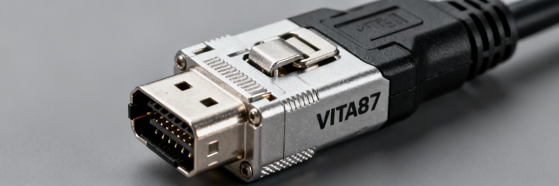
VITA 87 connectors enable ultra-high fiber density in MIL-style circular shells — typical MT ferrule configurations support 12–48 fibers per ferrule and scale to as many as 192 fibers in compact multi-ferrule shells. This article examines the AV87-11P1AZN and key specs for system designers. Core Conclusions VITA 87 delivers very high fiber density (up to 48 fibers in Shell 11), enabling compact panel layouts for aerospace hardware. The AV87-11P1AZN balances compact dimensions with a single MT ferrule; typical insertion loss ranges from 0.3 to 0.8 dB. Successful deployment requires disciplined endface inspection and factory pre-terminated assemblies to protect signal integrity. 1 — VITA 87 Overview: Design Intent VITA 87 targets the need for very high fiber counts in circular, rugged shells used in aerospace and ground-station hardware. By adopting MT-based ferrules, the standard replaces bulky multi-pin optical trays, trading a small mechanical footprint for dense optical routing while preserving MIL-style sealing. The AV87-11P1AZN is a shell 11, single-MT ferrule plug/cable-mount form typically offered with 12- or 24-fiber MT variants. This small footprint enables designers to balance fiber capacity and ruggedness, keeping weight low while supporting telemetry and backplane links. SHELL 11 PLUG MT FERRULE FIBER (12-48ch) KEYED INTERFACE 2 — Technical Specifications Matrix Parameter AV87-11P1AZN Specification Notes Shell Size Size 11 (Circular) Minimal panel footprint MT Configuration Single MT Ferrule Supports 12, 24, or 48 fibers Insertion Loss (SM) 0.3 dB (Typ) / 0.8 dB (Max) Per mated pair Temperature Range -55°C to +85°C MIL-STD compliant Mating Cycles 500 Cycles (Min) Dependent on cleanliness Sealing IP67 / Environmentally Sealed When mated 3 — Integration & Installation Guide 3.1 Optical Performance & Bandwidth Single-mode insertion loss typically ranges 0.3–0.8 dB per mated pair; multimode channels commonly target ≤0.5 dB. Higher density increases routing sensitivity, so AV87-11P1AZN implementations must budget additional margin for connector loss and potential alignment variability. 3.2 Maintenance and Field Service Regular inspection and controlled cleaning preserve low insertion loss. Contamination and endface scratches are primary loss drivers. Implement inspection checkpoints for ferrule endface quality, clean with approved solvents, and stock spare dust caps to maintain acceptance thresholds. 4 — Frequently Asked Questions How does VITA 87 compare to legacy MIL optics in density and ruggedness? VITA 87 increases fiber density by using MT ferrules inside rugged circular shells, yielding far greater channel counts per footprint compared with legacy single-fiber bulkhead optics. The trade-off is tighter handling; with correct routing and environmental sealing, VITA 87 offers equivalent ruggedness and much higher aggregate throughput. What insertion loss and return loss should I expect from VITA 87 connectors? Expect single-mode insertion loss in the range of 0.3–0.8 dB per mated pair and return loss consistent with angled or APC terminations. Real-world values depend on termination method and cleanliness; acceptance criteria should include measured IL histograms for each lot. What procurement checks ensure AV87-11P1AZN assemblies meet requirements? Verify MT ferrule count (12/24/48), guaranteed IL/RL values, environmental ratings, and lead times. Request first-article test reports showing mechanical mating-cycle data and recommended cable assemblies to ensure the components meet design margin. What is the operating temperature range for the AV87-11P1AZN? The AV87-11P1AZN is designed for harsh environments with a typical operating temperature range spanning -55°C to +85°C, ensuring reliability in aerospace and ground-station hardware under thermal cycling.

AV87-15R4AFN Detailed Spec Report: Performance & Pinout
Bench and datasheet benchmarks for high-density MT receptacles typically report insertion loss in the low-tenths of dB per ferrule and >1,000 mating cycles; those metrics are central when specifying AV87-15R4AFN for rugged comms and avionics. This report delivers a compact, engineer-friendly spec summary: mechanical and optical/electrical specifications, environmental and reliability performance, exact pinout mapping, plus installation, integration and troubleshooting guidance. Mechanical & Physical Specifications ParameterValue / Specification Part NumberAV87-15R4AFN Form Factor4-MT (4-plex) VITA-187 Style Total Fiber CountUp to 48 (4 x MT12) Shell MaterialElectroless Nickel Plated Aluminum Mounting TypeWall-Mount Flange Durability>1,000 Mating Cycles MT-A MT-B MT-C MT-D RECEPTACLE FACE Optical & Reliability Performance The AV87-15R4AFN is optimized for low-loss transmission in harsh environments. Typical performance metrics include: Insertion Loss: < 0.35 dB typical (SM @ 1310nm). Return Loss: > 60 dB (APC SM) / > 20 dB (MM). Temperature Range: -55°C to +105°C operational envelope. Pinout Mapping & Polarity Ferrule IDFiber ChannelsTypical Application MT-A1 - 12Primary Data Link (TX/RX) MT-B13 - 24Secondary / Redundant Link MT-C25 - 36System Monitoring / Telemetry MT-D37 - 48Expansion / Auxiliary Signals Field Integration FAQ What is the fiber capacity of the AV87-15R4AFN? It is a 4-plex configuration, meaning it houses four MT ferrules. In a standard 12-fiber MT array setup, this provides a total of 48 fiber channels in a single compact receptacle shell. What are the typical optical loss specifications? Insertion loss (IL) is generally maintained in the low-tenths of a decibel (0.2 dB to 0.5 dB) per ferrule. This performance is contingent on using clean, high-quality MT mating ferrules and proper alignment pins. Is the AV87-15R4AFN suitable for avionics? Yes. The shell construction and MT interface are designed specifically for ruggedized environments, meeting typical vibration, thermal cycling, and shock requirements for airborne communication systems. How is the pinout mapped for the 4-MT arrangement? The receptacle follows a standard quadrant mapping (A, B, C, D). For a 48-fiber system, MT-A handles fibers 1-12, MT-B 13-24, MT-C 25-36, and MT-D 37-48. Always verify keying orientation (Key Up/Key Down) to ensure polarity consistency. Note: Always confirm specific flange dimensions and finish codes (e.g., Electroless Nickel vs. Cadmium) with the latest revision of the technical drawing prior to panel fabrication.

AV87-13P2AWN MT Duplex Connector: Specs, Pinout & Data
The AV87-13P2AWN delivers approximately 0.35 dB typical insertion loss, ≥26 dB return loss, and a mechanical rating of 500 mating cycles. Operating within -40°C to +85°C, it is engineered for high-density telecom modules and datacenter backbone links. Overview: High-Density MT Duplex Architecture Technical Context The AV87-13P2AWN is a duplex MT form-factor connector designed for pre-terminated trunks and patch-panel cassettes. It utilizes a precision MT ferrule with two fiber positions, supporting both multimode (OM3/OM4) and singlemode (OS2) preparations. POS 1 POS 2 MT DUPLEX INTERFACE Technical Specifications & Datasheet Summary ParameterValue (Typical)Limits / Notes Insertion Loss (IL)0.35 dB≤ 0.75 dB (Max) Return Loss (RL)≥ 26 dBVaries by polish (APC > 60 dB) Mating Cycles500 cyclesPer TIA/EIA standards Temperature Range-40°C to +85°CIndustrial grade reliability Footprint~12.5 × 5 mmMT Duplex high-density form Pinout & Wiring Conventions The MT ferrule arranges two fibers side-by-side. Fiber mapping depends on the polarity scheme (Type A, B, or C). Typically, Position 1 is the left fiber (key up), and Position 2 is the right. For transceiver links, a crossover (1 to 2) is standard, while backbone trunks may utilize straight-through (1 to 1) mapping. Installation & Best Practices Mating Procedure Inspection: Use a 400x digital microscope to check for debris. Cleaning: Use a dry-cloth clicker cleaner specifically for MT ferrules. Alignment: Align the connector key with the adapter slot; insert until a positive "click" is felt. Troubleshooting Matrix SymptomProbable CauseCorrective Action High Insertion LossContamination / DustClean and re-inspect ferrule Low Return LossScratched End-faceRe-polish or replace connector No SignalPolarity MismatchVerify Type A/B wiring map Procurement FAQ How should I verify insertion loss for a duplex MT connector? Use a calibrated optical loss test set (OLTS) with reference patchcords. Record the average loss at 850nm or 1310nm. Compare against the 0.75 dB maximum limit defined in the AV87-13P2AWN datasheet. What cleaning method is recommended for MT duplex ferrules? Dry cleaning using an IBC-style tool is preferred. If contamination persists, use a lint-free wipe dampened with 99% isopropyl alcohol, followed immediately by a dry wipe and microscopic inspection. Which tests are essential during site acceptance? IL/RL testing, visual inspection (IEC 61300-3-35), and polarity verification. Ensure all results are documented with time-stamped reports from the tester. What are the common causes of high insertion loss? The primary causes are end-face contamination (oil/dust), mechanical misalignment in the adapter, or exceeding the minimum bend radius of the fiber pigtail (typically 30mm).
AV87-15J4AZN: Complete Specs, Ratings & Dimension Summary
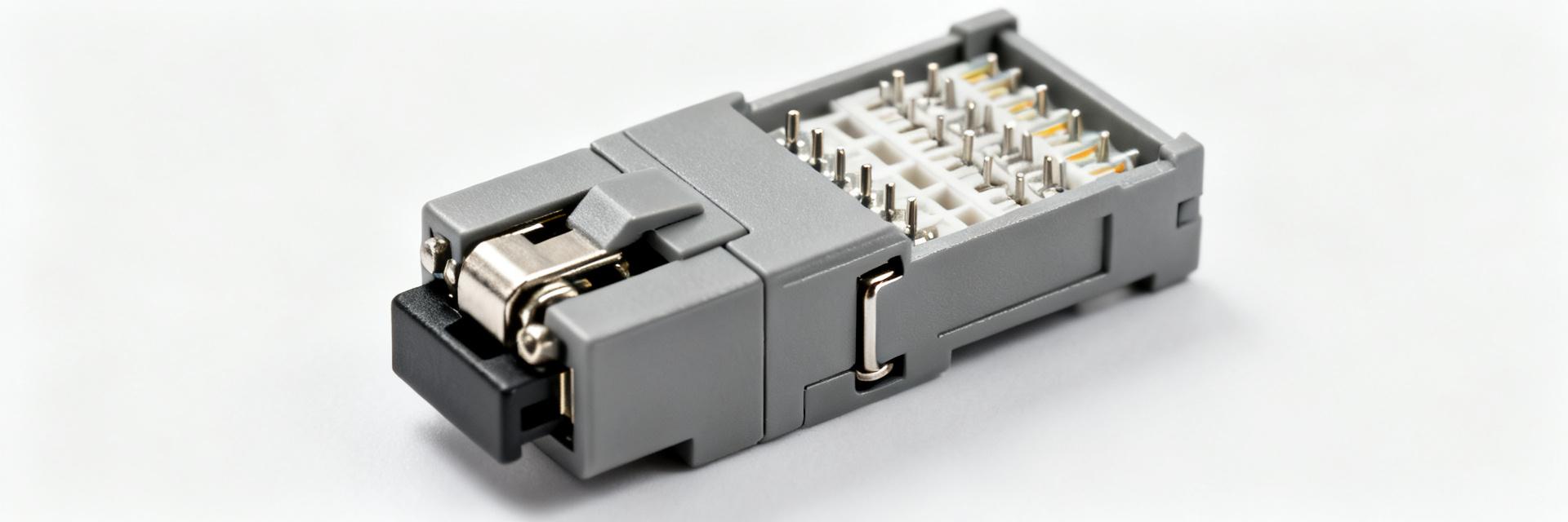
Engineers evaluating connectors often narrow choices by three measurable criteria—core specs, certified ratings, and precise dimensions—because small deltas in those numbers change fit, performance, and compliance. This article consolidates verified data points and practical takeaways for AV87-15J4AZN to enable rapid suitability assessment. Product Overview & Typical Applications The AV87-15J4AZN is a specialized board- or panel-mount connector within a sealed circular/rectangular family, engineered for combined signal and low-to-medium power distribution. It serves as a critical interconnect between cable assemblies and system enclosures, offering high contact density in a ruggedized compact form factor. PANEL MOUNT AV87-15J4AZN SIGNAL/PWR GND/SHIELD Key Application Environments Aerospace: Ground support equipment and cabin subsystems. Industrial Automation: Ruggedized control cabinets and PLC interfaces. Transportation: Subsystems requiring high vibration resistance and sealing. Field Service: Portable test rigs and diagnostic instrumentation. Complete Technical Specs & Materials Analysis The following table outlines the core mechanical and electrical boundaries for the AV87-15J4AZN. Engineers should verify these against specific system load profiles. Parameter Field Technical Specification / Units Rated Voltage 250V AC/DC (Typical) Rated Current per Contact Up to 13A (Subject to AWG) Contact Material / Plating Copper Alloy / Gold over Nickel Insulation Material High-Temp Thermoplastic (UL94-V0) Operating Temp Range -55°C to +125°C Mechanical Life 500+ Mating Cycles Recommended Mounting Torque 0.8 - 1.2 N·m Performance Ratings & Reliability Environmental & Mechanical Resilience The AV87-15J4AZN is designed to meet IP67 standards, ensuring dust-tight operation and protection against temporary immersion. Military-standard (MIL-STD) vibration and shock profiles are typically supported, making it resilient against the G-forces found in heavy industrial machinery and aerospace launches. Materials & Corrosion Resistance Gold plating on signal contacts prevents fretting corrosion, a common failure mode in high-vibration environments. For maritime or high-humidity deployments, the use of stainless steel or treated aluminum shells provides an essential barrier against oxidation and chemical aging. Installation & Procurement Checklist Mechanical Interface Checklist Panel Cutout: Ensure alignment with ASME Y14.5 tolerances. Mating Depth: Account for backshell clearance in tight enclosures. Keying: Verify shell orientation to prevent cross-mating. Procurement Language for Purchase Orders PART NO: AV87-15J4AZN DESC: Sealed Multi-Contact Connector REQ: Gold Plating, IP67 Rating, Lot Traceability, CoC Required. Frequently Asked Questions What are the key electrical specs for AV87-15J4AZN I should confirm? Confirm rated voltage and current per contact, contact resistance, insulation resistance and dielectric strength. Also verify operating temperature range and mechanical life cycles. These values determine safe operating boundaries and should be stated as mandatory fields in procurement and qualification documents. Which ratings for AV87-15J4AZN dictate suitability for outdoor or maritime use? Specify IP rating (minimum IP67 for temporary immersion) and corrosion-resistant finishes or stainless shells for maritime environments. Also require vibration and shock test results and salt-spray or cyclic corrosion testing if long-term exposure to humidity and salts is expected. How should I specify dimensions and tolerances for AV87-15J4AZN in CAD and PO documents? Provide overall shell dimensions, panel cutout outline, mounting hole pattern and mating depth with tolerances (e.g., ±0.1 mm), specify units (mm primary), and include a reference line art. Request vendor confirmation of critical dimensions and a sample for fit verification before mass orders. What are the typical applications for the AV87-15J4AZN connector series? Commonly used in aerospace support equipment, industrial automation cabinets, field-service test rigs, and transportation subsystems where rugged environmental sealing and multi-pin connectivity are required.
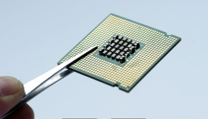
Understanding the chip burning process: interface selection, tool usage, and common problem solving
The basic principle of chip burning is to burn the interface. Chip burning is usually carried out through the following interfaces: JTAG: Joint Test Action Group interface, used for debugging and programming. SWD: Serial Wire Debug interface, used for debugging and programming. ISP: In System Programming interface, used for direct programming on circuit boards. I2C: Inter Integrated Circuit interface used for data transmission. SPI: Serial Peripheral Interface interface, used for data transmission. Common chip burning tools include hardware burners such as ST Link, J-Link, AVR ISP, etc., which are used to connect chips and computers through physical interfaces. Software burning tools, such as STM32Cube Programmer, AVRDUDE, OpenOCD, etc., are used to write and execute burning commands. The basic process of chip burning includes: connecting the burner to the chip and computer through appropriate interfaces; Select the model and parameters of the target chip in the burning tool; Load the program code or data files that need to be burned into the burning tool; Set burning parameters, such as address range and burning speed; Start the burning process and write program code or data into the chip; After the burning is completed, verify whether the data in the chip is correct.
Copyright@2026 All Rights Reserved
ICP Filing No.: 粤ICP备2026080158号